
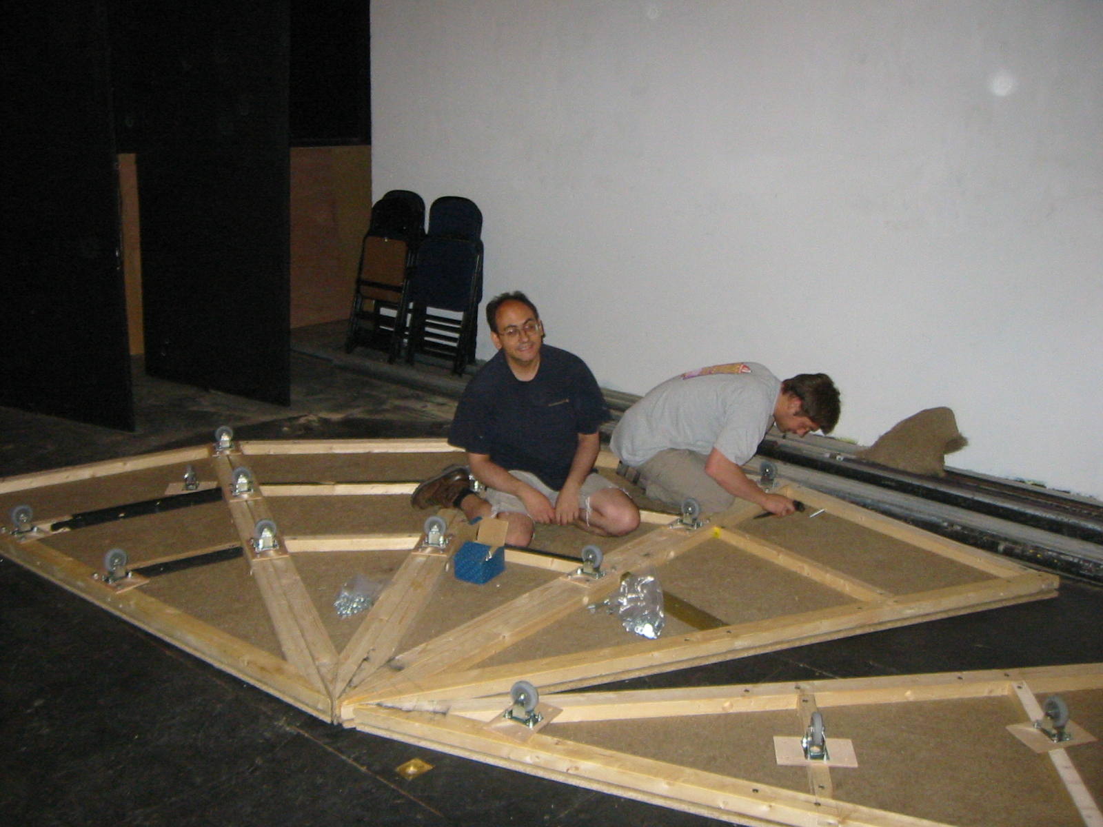
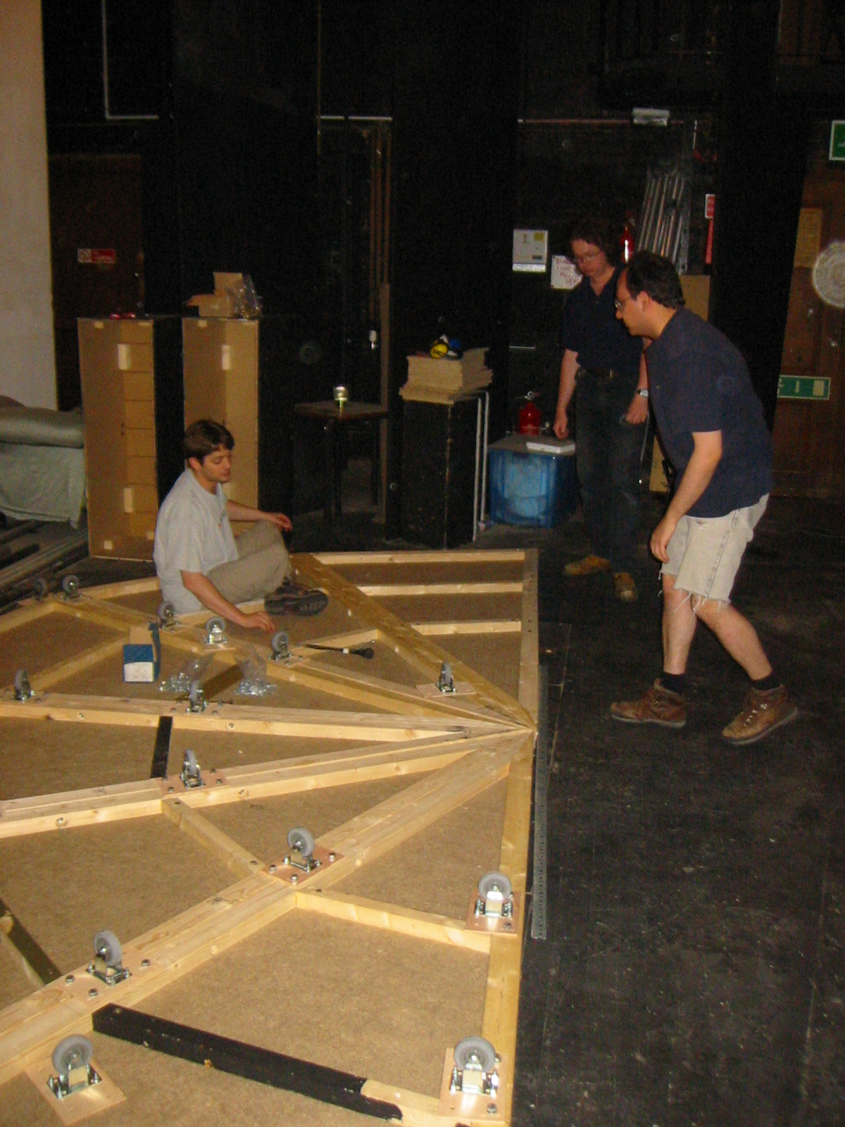
A very hectic day, lots of crew in including Laurie, Alli and Tanya to help paint, and Austing, Gus and Paul to help build things.
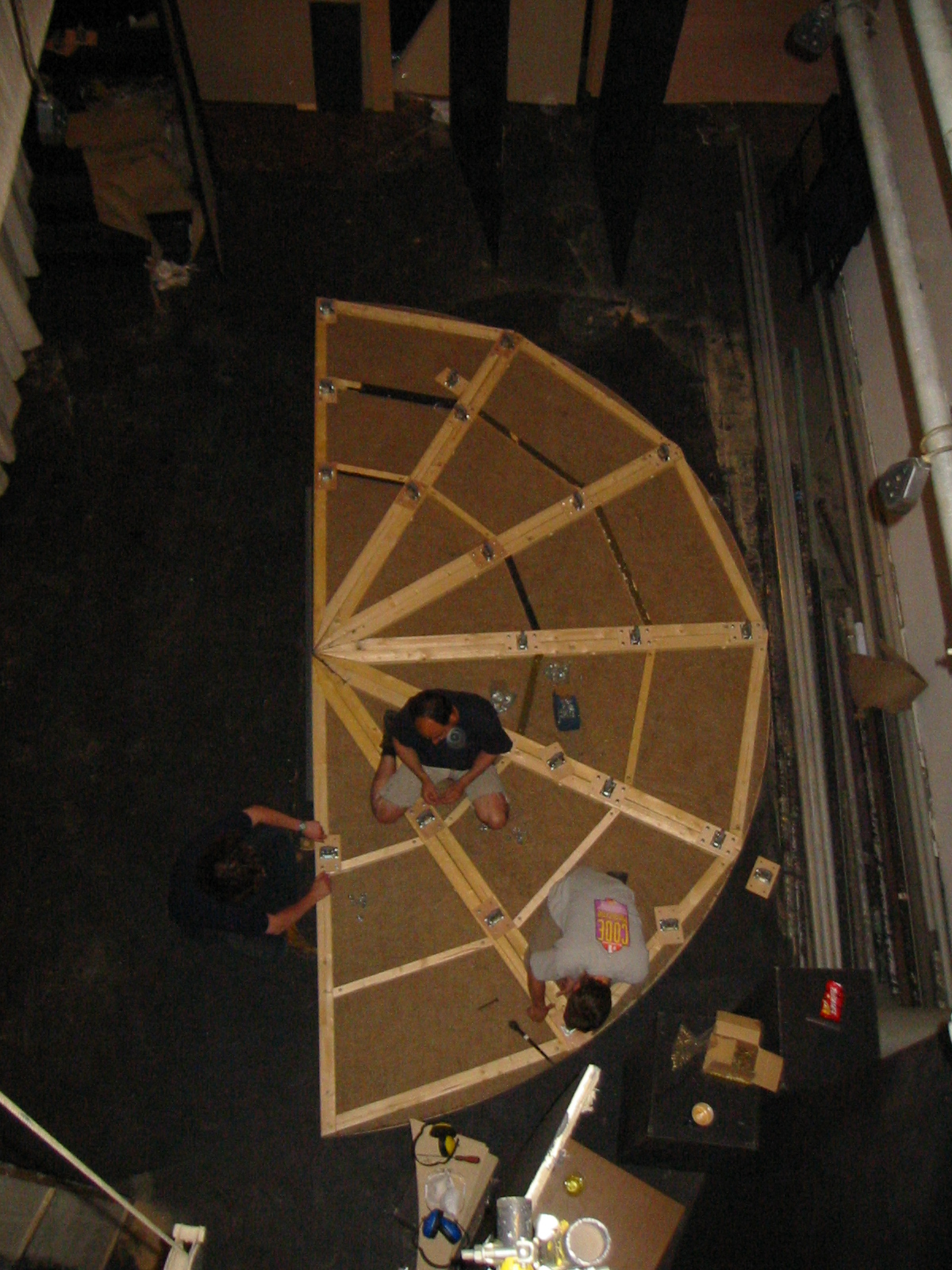
Marked and drilled the final 4 revolve tops, felted and assembled onto their frames. Frames were then trimmed flush to their tops befure being dismantled for painting. Once the paint had dried the M10 inserts were re-insterted, tops re-attatched to frames and the half revolves assembled ready for drilling of the center plate mountings. Both revolves assembled so that their front edges was within a couple millimeters.
Meanwhile various stateroom flat frames were being skinned in the 3mm ply. Enough of these were done such that they could be assembled onto one of the revolves that had been flipped onto it's wheels to allow everyone to get an idea of the size of the staterooms and how they fit together with the various bits of bracing. This also proved that the formed center flats fit around the pivot pole in the manner expected.
Paul noted that some of the inserts are working loose, probably due to being screwed in and out too many times. These will need to be expoy'd into place at some point.
News from Dan Young that the stage and floor of the hall in Budleigh have been sanded and varnished. This is a nightmare for us since it means that none of the set can be fixed directly to the floor, also all of the steeldecks will need to be placed on shims, and the legs footed and placed on shims. Wooden support legs will need to be cross braced to each other rather than being attatched to the floor, more of a concern for the stage left corner where it is all woodwork rather than decking. Will also need to tie the steps into the staging to stop them sliding forward when the gangplank is used. Painting will need to be done on dust sheets, also need to be carefull about workbenches scratching the floor, and moving the backstage cupboards around.
The aim for next weekend is:
| Saturday |
|
|---|---|
| Sunday |
|
Luke finished off the two bracing frameworks with their angled joints. Assembled the final three revolve frames. Assembled numerous state room frames. Cut down the brig door so that it has a flush top, and
Constructed the center plate with it's 50mm hole and two peg plates that hold a piece of curved metal around the back of the pivot beam.
Went into college via Flints to pick up a some Peg plates to build the pivot points.
Routed a bunch more lap joints for the various stateroom flats. Assembled one frame to check that the joints are all working.
Drilled the formed vertical to accept long M10 bolts, assembled and verified that they do indeed from a 45 degree angle. Set up the router jig for a 23.5mm depth and cut the joints for the first frame, a porthole frame as determined by it's two support beams. The non-porthole frames will just need some form of beam around the midpoint.
With luck, I should be able to get ahead of the others allowing them to make up one revolve frame, followed by a stateroom frame or two since the frames only need the small fret cramps which we have plenty of.
Also found more of the long M10 bolts, which means that the remaining revolve sections don't neccessarily need to be drilled out to a 50mm counterbore.
Still need to work out how to attatch the half clip that holds the half-revolve onto the pole. Ideally it should be attatched the the center plate rather than the revolve sections themselves. Suggest two stud plates per center plate from Flints recessed into the plate.
Cut the formed verticals for the staterooms that make up the 45 degree angle.
Moved the final two decks upstairs.
Two more decks have been brought across from Mary's.
Replied to Hannah, one of Dan's harem that will be helping out with the painting. Reproduced here because the links are useful.
|
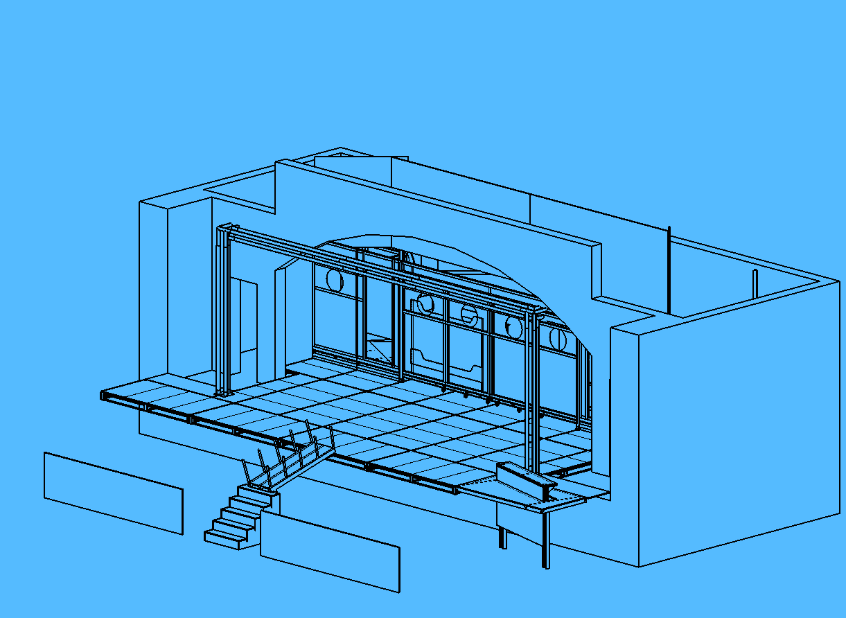
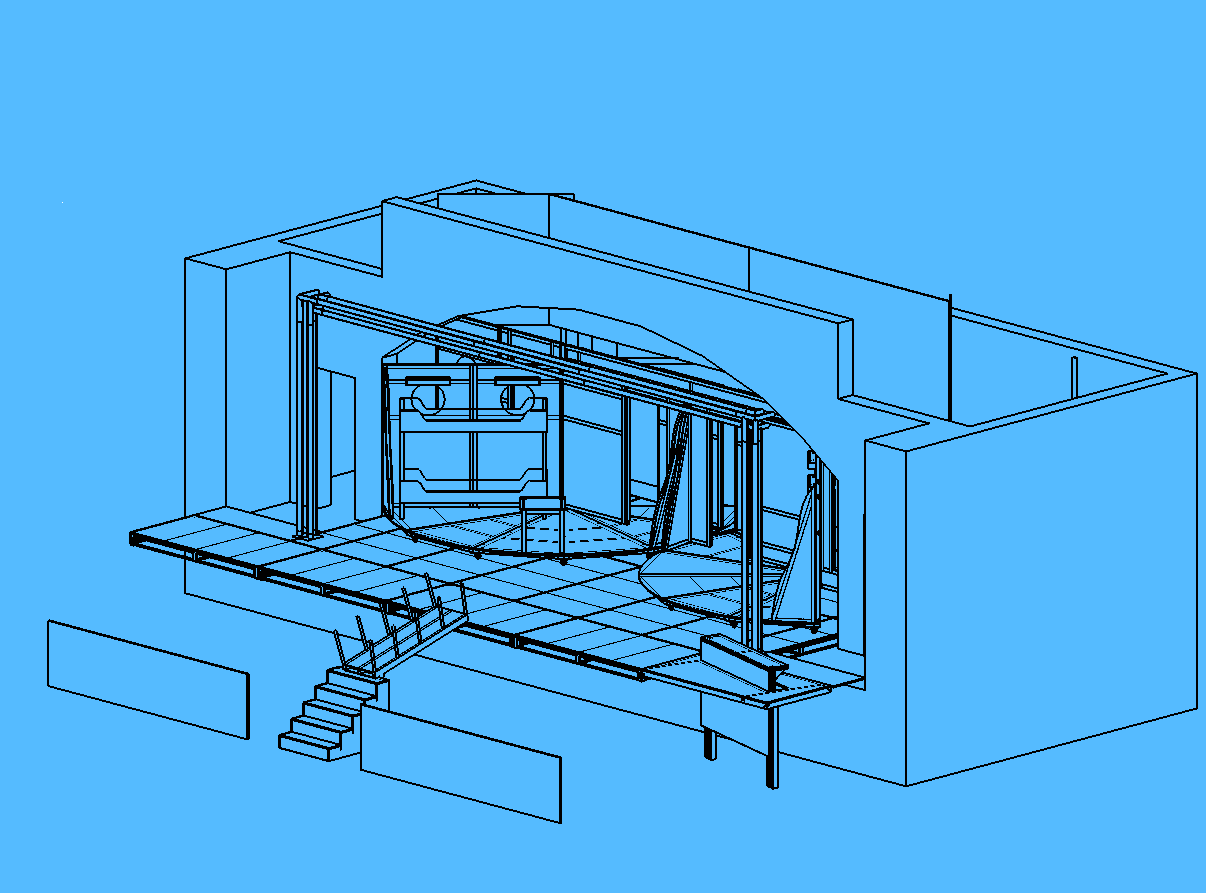
As such, there isn't really a backdrop. Due to my own personal lack of painting ability most of the sets that I design tend to be fairly structural rather than relying on painted backdrops. The set itself is comprised of a false backwall designed to look like the side of a large oceangoing liner, painted white with various portholes and doors. From behind this false wall various characters staterooms appear. The intention for the staterooms is to use woodstain and varnish on plywood to give the effect of wood panelling. Typically the staterooms would have veneering using different woods as decoration, the intention here is to use different coloured woodstains to simulate the veneering, specifically I'm thinking of the doors to the cabins, although a similar treatment may well be needed on some of the furniture pieces that we'll be constructiong.
For a rough view of what the set should like, the following two images are a fairly good example.
I have bid on the following set of light fittings on EBay for use in the
staterooms, however it seems likely that the seller isn't going to dispatch
them therefore I'll probably end up making moulds and casting a set in
fibreglass. The important thing is that it is the clamshell motif from the
lamps that would be good to transfer into the veneer decoration on the
doors.
The following two images are lift doors in the Chrysler building, possibly
a bit over the top compared to what is needed in the cabins, but an
example of the sort of thing that qualifies as Art Deco.
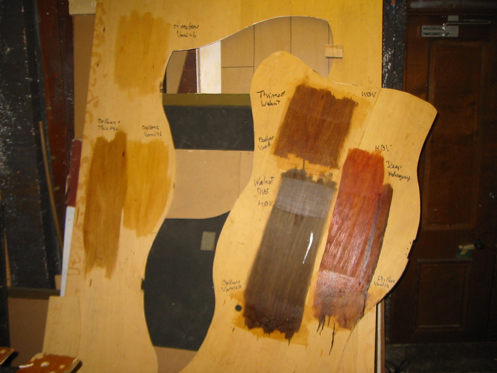
I've already done some test samples with the woodstain shown in the
following photo. The staterooms will probably use thinned walnut with the
Bollom's varnish. The other test samples offer an example of the colours
that can be achieved for the veneering effect.
The final piece of the staterooms jigsaw is that I would quite like a piece
of period art on the wall of one of the staterooms. One of the more famous
artists of the period is Tamara Lempicka (coincidentally an exhibiton of
hers is currently on at the Royal Accademy). The most famous painting is a
self portrait of her, although I do have a book of her other paintings. I'm
not sure whether it is worth trying to get someone to make a copy of the
painting in her style, or whether it would be easier to buy a poster and
frame that. My main worry is that the poster could look too shiny under the
stage lights.
One of the staterooms is actually the ships brig, this will be painted grey. It needs sensbile rust effects applied, and maybe the odd bit of graffiti from previous inmates.
The final artistic piece is a logo for the dockside bar that opens the
show, this logo might also be on the crew T-Shirts if I ever get around
to organising them.
|
Picked up enough timber to complete the pieces for the remaining revolve frames. Assembled two more frames.
Started Luke building the two bracing sections for the staterooms.
Determined that the old 9" circular saw will be needed to flush trim the deck frames.
Deck shift, although we're two decks short at the moment.
Dismantled the revolve. Need to remember to get some deep throat sockets, also need to work out which bolts will be used. The design calls for the counterbores on the revolve segments to be 50mm deep, these will have to be increased when the frames are dismantled to be painted.
The kiddies have moved the decks across from Mary's, but they still need carrying upstairs, and because they loaded them into the quad this means twice the number of flights of stairs that they have to be carried up. Am concerned that it will only be Luke and myself tomorrow in order to do this which doesn't bode well given that I'm bogged down with a horriffic cold at the moment.
Need to work out how to get the circular saw to cut precisely parallel to the edge of the deck tops. Possibly some form of plate bolted onto the base of the saw if there are suitable mounting points.
Considering whether the ripple tubes could be done by cutting the plastic tubing we already have with a jigsaw. The only concern is whether the plastic can take the heat from a bank of linear lamps. Intend to spend the afternoon seeing whether the tubing can be cut into a sufficient pattern, and how it warms in proximity to a coda fixture.
Also need to start shaping the wood for the flats properly.
Still need to model the front of house bracing that will support the goalpost since this
Tried to work on cutting a ripple tube, but got side tracked into cleaning up the 2nd floor foyer in order to keep the LFB fire officer happy. We now have plenty of wood suitable for the bonfire, just need some means of getting it there sensibly. Held back one palette with the intention of putting cators on it and strapping the revolve segments to it. Also need to put castors onto my drill box at some point to facilitate it's movement.
3 additional bulkhead fittings came from Screwfix, one of which got damaged in transit. However, this makes 10 usable fittings and 1 damaged but repairable.
Trying to work out if the ripple tubes can be done purely by reflecting light off of a circular tube. Suspicion is that too much light would be wasted meaning that the reflections would be too dim. A pass through mechanism would be better, but how do we construct the tubes.
R7S holders for linear lamps are a couple of quid from RS, might be able to source them more cheaply from the local shop on Gloucester road, will have to enquire.
Got enough segments ssembled to form a complete semi-circle, assembled another 27 or so castor plates, this time with larger 12.5mm boltholes.
Proved that the revolve worked, could push three people on it with some force, pulling is easier because the push applies a downwards force that creates more friction. The revolve deviated by about an inch from it's axis during a revolution. The center points also requires a plate to hold them all together otherwise they sag when you step to near the center. The plate will also act as the bearing on the fixed pole.
 |
 |
 |
 |
Had to leave assembled as there weren't enough people to flip it onto it's back for dismantling. 4 people can flip it over, needs 6 to get is back because the castors need footing.
Need to get hold of some 17mm deep throat sockets in order to tighten the bolts between the revolve segments. May need to source additional bolts, or recess the holes even further to allow th 70mm bolts to be used.
Cut all 12 segments, used a jig bolted onto the corner of the chipboard to act as the pivot point for a long radial arm that the router could be attatched to. Everything seems to be working out correctly, the segments have a 2440 length from the point up to where the arc intersects the top of the board, therefore they must be 30degrees.
Glued the felt onto two segments, enough to make up two full sections that could be bolted together.
Assembled 10 castor plates.
Weighed a revolve segment, weighs exactly 30kg.
Bulkhead fittings and handles have arrived.
Conserding whether it would be possible to make a mould from the fittings sourced on ebay in order to make desklamps and table lamps using the clamshell motif? Need some form of material to make the actual mould, then something to create the casted shell. Options are papier-mache, cellastic, or fibre-glass. Papier-mache is risky given that it is going to be part of a desk lamp, cellastic is a plastic material that would need to be sourced from somewhere. The other option is fibreglass which is interesting because I need some fibreglass to complete some repairs and modifications to the car.
Managed to get another 8 long members for the revolve segments, cut, morticed, drilled for inserts, drilled for bolts. Additionally 4 of them had recieved counterbores for the boltholes. Still remaining is to clean up the 15 degree cut and drill the dowel holes.
Due to the lengths of wood supplied, I have noticed that we are running short of 3x2PAR. Will probably have to pick up a pack from B&Q, something like 6off 2.5m lengths.
The correct castors have arrived from Flints.
Helped Dan repair the wheelchair since the rubber on the front tyres is in bad condition. Reglued the tyres to the rims, but it is likely that fresh wheels will have to be purchased, RS seemed to be doing them for around �5 a piece. Thankfully this will go onto the props budget.
Noted that the coffee table lurking in the props cupboard, if sanded down, re-stained and revarnished would make a very good Art-Deco coffee table.
Ordered a set of 3 double and 6 single wall lights in Art Deco style with shell design shades, all for �32 from EBay. Need to transfer that shell design into the door panel and bed details.
My thoughts on the door panels are to draw the pattern in either black marker or black paint, and then paint by numbers using various shades of woodstain to fill in the gaps. If we think it's necessarry then everything can be covered in varnish.
Found bulkhead lights on Screwfix for �1.99 each, inc VAT. ordered 10. Will probably use 4 on the lower section of the ship, and another 4 on the upper section. The remaining two will be for lighting in the corridors. Also ordered some doorhandles suitable for the two exterior doors.
Thinking about it, the entire set is now thoroughly laced with practicals which should keep the Lx crew busy for most of the setup. Current count is:
Thank god for the Avo rack is the only thing I can say. Have to hope that it is capable of running the low wattages without too many problems.
Do need to go back over the Lx plot to ensure that there are enough channels and also to work out how it should be cabled wrt to Leci runs etc...
Managed to get most of the drilling in a further two long beams, and also one end member cut and drilled. Have decided that the priority is probably to press on with marking up and cutting the long beams since they take such a long time to cut on the morticing unit. Use of a larger bit would help, although the fences are now set up for the 8mm bit.
Thinking more about interior design of the staterooms. Looking at Art Deco in particular. Might be useful to go and visit the Tamara Lempicka exhibition at the Royal Academy. The green bugatti picture might go very well in Eli's room. Considering taking the chaise lounge for use in that room, set against the wall.
Need to work out a design for the doors, and possibly source some alternate woodstain to provide different colours, check the paint cupboard. It might also be useful to work out an Art Deco headboard for the bed and bunkbeds.
Still need to source some Art Deco objects to fill the various rooms, ie. vases, clocks and mirrors.
Painted up a couple of test patches of plywood with differing woodstains and varnish combinations.
Attempted to cut two of the final members that are required to complete the next two frames. Cut both wrongly, gave up and went home to tackle the car instead.
Finished cutting all of the tenons on the 2x2 cross members, assembled another two frames, although one didn't pull together at the point correctly so might have to be dismantled.
Have enough long members to allow another two frames to be built up over the course of the week, the intention is to have 6 frame available to be topped and test-assembled into a revolve by next Saturday.
Marked up a number of main beams for the revolve frames, got Luke set up on the morticing unit gouging out the motice holes. Prepared enough of the cross members to build up a frame to check that everything works.
Assembled frame, everything looks like it's going to line up reasonably well.
Used the keyhole saw to cut the haunches in the main beams of the revolve frame. Used a 1 1/4" Forstner bit for the deck counterbores. Used wedges that came out of the 15degree cuts to make suitable clamping faces at the point of the frame. Need to make sure that the faces meet and form a good point otherwise they wont fit the top deck properly and consequently the
Built up a 15 degree plate for the morticing unit, on the second attempt using thicker facings it is working well. Added two fences to get the alignment correct. It still needs some form of far prop in order to allow morticing at the very extremes.
Cut all of the 2x2 members to lentght and drilled them to accept the M10 insert, but didn't add the insert because they need to be painted black first and adding the inserts first would cause the threads to get clogged with paint.
Cut the tenons for one member to check that it could be done and ensure that they were the correct distance appart.
Remainder of the Flints order arrived, nboted that I'd specified the wrong castors and hence we have ended up with Nylon rather than Revolite castors, and 6 castors too few. To counteract the nylon we could put flooring down, I may also have a couple of identical castors in the chairstore left over from Sorceror.
Running off various drawings to enable the staterooms sections to be built, principally the details that I need in order to make up the formed sections around the pivot.
Axminster orders has arrived. Dowels were slightly smaller than the pervious set, but this shouldn't be too much of a problem given that they are being used in a 2x8 grid. Morticing unit is working a treat, need to fabricate the 15 degree baseplate for it.
Have now marked up all of the 2x2 revolve members ready for the weekend.
Scaff arrived.
Assembled the second raising bar mechanism.
Built the 15degree jig, although concerned that the circular saw isn't qutie deep enough to cut right the way through. Will have to test on a scrap piece to see if we can then use it as a guide cut and finish it off with hand saw.
For the revolve I have decided to use planed 2x2 from the stock pile rather than the 2x2 ordered from TP since it is nicer and being planed it fits with the planed 3x2 that we have. Started marking up the the revolve cross members, takes about 10minutes per member. Have 18 out of 24 left to do, with another 12 3x2 members and 24 main beams. Will probably need to spend the best part of a day marking everything up.
Still waiting for the Axminster order.
Made up the PNE to 3PNE adaptor that will be used to send the same phase to all three parts of the Avo rack.
Added the trilite and gangplank to the set. Remodelled the gangplank to 6ft, this means that the pit rail will lie level with the downstage edge of the table cupboard door.
Tinkered with designs for the 15degree cutting jig.
Picked up a �15 CD player from Argos to keep me amused.
Flints order has arrived, except for castors, underfelt and scaff.
Started marking up one of the main beams for a revolve segment, takes about 30minutes per piece. Tried to cut a mortise by hand, but chiseling it out doesn't get the nice clean square hole that I'm after. Had to tinker with some of the dimensions since the timber is 47x70 rather than 47x75 as originally assumed.
Placed the Axminster order.
Carved the two H shaped members for the raising bar. Used two passes per side of the 10mm rebate cutter to create two of the four T shaped fixed slides. Carved the relevant holes for the pulleys and assembled one unit. A little bit sticky at times, but that should pass as more weight is applied. It shouldn't take more than an hour to fix up the second one.
When routing, always have the cutter running into the wood if the reverse side is open, since this provides a cleaner cut and stops the router trying to run away.
Wood order has arrived. 3x2 timber is almost planed, with chamfered edges. All looks fairly dry, with minimal bowing.
Pondered the demountable flats problem on the way into college on the bus. It looks like it makes the most sense to make the brig walss demountable and use fittings like the porthole lightboxes to provide support and holding for the walls.
Finished bracing engineering drawings. Assembling the cutouts into the model to see how much they are likely to mask the staterooms. It looks like the sightlines on the cutouts will be fine, could do with sketching through to verify this however. I wonder if there is functionality to position a camera within the model?
The mating within the main assembly has been trashed, have ditched the existing setup and will start again from scratch. Suspect that trying to shuffle things around when components were suppressed cause the problems.
Fully modelled the doors and arch for Budleigh stage.
Have reorganised all of the CAD components so that they are now in a higher level directory and write protected. Accidentally trashed the castor component, although have realised that I might have uploaded it to the Dramsoc website, so can possibly recover it from there.
Would like to model a universal clamp, but DNS resolution appears to be shafted so can't get to the doughty website to try and find dimensional information.
Started putting together drawings for the Raising Bar insert, and the stateroom bracing. It's going to be a long slog to get all of the parts turned into full working drawings.
Tinkering with the rotation tools, trying to get the revolves to move around the scaff axis smoothly.
The Budget castors don't get the 15% discount that I'd been hoping for. Have had to downgrade to Revvo Series 2 castors, which were the only castors at a sensible price that would fit the 113mm depth. Have to increase the depth of the ply that the castors are attatched to to 15mm. Weight loading is 36kg per castor, which for a single revolve equates to 216kg max. Total loading of 648kg per revolve.
Modelled gangplank and assembled it along with the steps to make the pit rail. Concerned that the pit is a long way forward of the original budleigh stage. Might need to shorten the gangplank down to 6' to reduce the pit to just 8' depth. This would also improve the structure of the gangplank so that it doesn't have to take as much weight across such a large span. Still undecided as to whether the gangplank should have rails or not since these will look out of place in the opening bar scene.
Still trying to source a large format plotter on Ebay.
Have got the Trilite bar into the CAD package, but it still goes off into space when I try to float the trilite structure to position it properly. I'm considering just leaving it where it is, it is within a couple of inches of where it should be and the precise alignment isn't crucial as far as the CAD work is concerned.
Might be worth taking the spare baseplates since it might be possible to bolt these to the Budleigh flats some how, and therefore provide more support to the structure. Need to check that the baseplates have boltholes, and if necessary put some discrete 10mm holes into them.
Need to make sure we have a sensible supply of coach bolts, and the relevant washers so that they can be fitted to the keyclamps and trilite base units. M6 would be preferable since I know we've already got a supply of these, and they aren't too long.
An idea for supporting the upper level flats. Use a universal clamp upside down, with an M10 bolt onto a stage brace up to the flat itself.
Martin has requested a kit list to pass onto Rich so that he doesn't try to hire out the stuff we need over the summer.
Trying to model the trilite proscenium, but the CAD package keeps going off into an apparently infinite loop when I try to mate additional pieces of trilite.
Need to start on producing the various drawings required for the flats and other scenic items.
Found 4off 8' lengths of planed timber in the chairstore that will be suitable for the bunk uprights.
Tried making the groove and rib for the raising bars sliding joint. When cutting the groove need to do it in two passes so that any walk occurs towards the center of the groove. Use an 8mm cutter, dont force the cutter when making the deep cuts in the H shaped timber. The wheel scribe has a guage on it, therefore it can be used to accurately mark lines along the timber. Need to ensure a good fit, free but without too much slop. Cut over length pieces since the ends will inevitably be a bit of a mess and can therefore be cut off. Clamp timber either side of the piece being cut to give the router a solid base so that it doesn't wobble.
Need to take the carpet tiles for backstage if people are going to be wearing tap shoes a lot!
Need to remember to order black paint from Flints with the next order.
Modelled the bunkbed.
Further work on the reassembled set. Should now be in a fit state to attempt modelling the scaff bracing. Could also do with modelling the pit and gangplank.
Concerned about the 2ft flats that act as masking on either side, at their current 45 degree angle they don't leave much room for access. Actually, it wasn't as bad as I at first thought because I'd got the modelling of the stage slightly wrong. Adding infill sections made up of the spare chipboard from the revolve to the DS wings.
Cleared up the chairstore and built a ramp for getting roadboxes in and out of the Union. Found some material that might come in handy for curtains since it's green.
Modelled the new steps that need to be built.
Began rebuilding the set making sure that all of the mates are working correctly.
Modelled a rough outline of Budleigh to check where the various set pieces would fall with respect to the various doorways.
Need to arrange the Axminster order so that all of the required tools are ready for the end of the month.
Thoughts on revolve fixing and skirting. Skirting will probably be done using spare black material. For the fixings on the visible side of the revolve that stop it pulling away from the pivot, suggest a section from a boom arm, with appropriate spacers so that it doesn't bind. Still unclear on fixings into the revolve, inserts would be neatest, but suspect that they won't be strong enough. M10 coachbolts through a number of decks would be the other option but would "damage" the revolve. Could try to mount a boss plate or insert within the join before it's assembled, although not sure that there is enough width to allow this to happen.
Research for T-Shirts, obtained numerous Art-Deco fonts that could be used. Drew the Jack Rose logo in draw and converted to WMF for transfer to the PC. Waiting for
Working on a rough timeline for the build up,
| 5th, 6th | Marking, Jig Construction |
| 12th, 13th | Shaped Timber, Revolve Flats |
| 19th, 20th | Revolve test joints |
| End Of Term | |
| 26th, 27th | Deck shift, BBQ, Revolve |
| 3rd, 4th | Revolve |
| 10th, 11th | Revolve Flats |
| 17th, 18th | Assembly, Scaff, Infill's, Revolve Flats |
I don't expect many people to assist until after the end of term, before that only a handful of people will be required. Indeed through the earlier people not having too many people around whilst the tricky woodwork is done.
Surveyed the current stock of keyclamps:
| A2 | Short Tee | 7 |
| A4 | Long Tee | 4 |
| A6 | Elbow | 7 |
| A10 | Round Base | 7 |
| A12 | Oval Base | 15 |
| A18 | 3 Way Elbow | 2 |
| A20 | 3 Way Tee | 7 |
| A22 | Right Angle Joiner | 2 |
| A34 | Small Wall Fixing | 1 |
| A44 | Flexible Side Coupler | 6 |
Enough couplers are available to do all of the reqiured structure for the revolves and lower flats. The flexible side couplers are the limiting factor, but careful inter-mixing of standard swivel clamps at points where the joints aren't required to lie flush, should allow sufficient bracing to be introduced. Could still do with some floor mount flexible couplers, but given the current budget situation it may be prudent to use
May have to consider reusing a large chunk of last years scaff legs and adding a barrel joiner and 6" stubs to them. This should hopefully free up a considerable amount of the newly pruchased scaff for the precise lengths that are needed in the support structure.
Spoke to Martin, he's placed the Flints order and is getting the TP order organised. Which also means it's too late to add anything else to the
Modelled a handful of trilite sections to check that the FOH bar would fit in roughly the right place. Should frame the proscenium fairly closely. Started trying to fit the to the existing set, but it destroyed the current mating arrangements.
Started compiling a list of equipment that needs to go down on tour from a set point of view, ie. the scaff clamps, treads, tabs, flats, etc...
Still can't get the CAD package to behave how I want it to, suspect that this is due to the various components not lining up quite perfectly because the orignal 8x4 decks were modelled using 8'x4' rather than 2440mmx1200mm. Have abandoned any more bracing, favouring the empirical approach once it's up. Will probably have to put in at order for 10-12 keyclamps from Flints, and do a hand sketch so that we know where to put the clamps.
Started thinking about paint and colour schemes.
Also musing over equipment location. Need to put the FOH Racks SL below the apron to give plenty of wing space. Probably worth putting the amp rack SR below the apron to keep it out of the way.
Modelled a couple more keyclamps in an effort to fit some bracing to the scaff structure, although at this juncture we have now reached the point of dimishing returns on extending the design any further.
Modelled the 6' flats that sit on the scaff structure, various infills including the one supporting the rear of the revolves, and the two 6x2 infills out front.
Modellde the 2x8 decks and rearranged the decks such that the boltholes will line up correctly. In the previous arrangement with the decks staggered none of the boltholes would have lines up which would have made holding the decks together tricky, a problem already seen in previous years. Noted that the existing 8x4 decks had been modelled to 8ft rather than 2440.
Reorganised the relationships such that the scaff structure lies against the back wall and dictates where the pivots for the revolves, and hence the boat facing lie. This in turn means that the castors of the revolves just fit onto the two infills.
Various notes regarding what bracing could be employed to ensure that the pivot scaffolding remains rigid. Will need to reserve some of the offcuts from cutting the deck tops to turn into an infill so that the cast can pass between the two revolves easily for the stateroom scene.
Finished the Insert, by adding the deck of the raising bar, a 2x1 structure and brackets. Started combining all of this into TheSet assembly and began building up the second revolve. Remaining pieces of structure that still need to be modelled are the small header sections above the revolve flats, and the rest of the support structure, which will also start to show how the support structure can be tied into the fabric of the building.
Finished modelling the far prompt side revolve, added the fixed flats. Added the scaff support structure for the upper levels, and the header across the top of the revolve flats. Haven't modeled any of the bracing or fixings, will probably play this by ear once it's assembled in the Concert Hall
Mailed Gary to get him to transfer the ICSM replacement stairs funds across to the Opsoc account.
Started work on the insert for the raising bar, although the geometry of it is causing me headaches trying to get everything to line up correctly.
Finalised the Flints and TP orders and mailed them to Martin. Shaved another �20 off of the TP order by finding some cheaper 18mm ply, but noticed that the Flints order will be �20 more expensive because the price of the slit drapes has gone up.
Went through the various items that need to be constructed listing the various resources they will require. The drillpress and router are likely to be the limiting factors. If a morticer is purchased then this can be used as a second drill press, and a second jig capable of cutting the 15 degree tenon shoulds is going to have to be constructed, so it would make sense to construct it for the smaller Dramsoc router because it doesn't have to cut such deep slots, and each shoulder was going to require multiple passes regardless.
Had a slight rethink about getting the angles on the shaped timbers. For really accurate angles the easiest way is going to be using bevel edge cutters on the router. The only downside is that the two cutters required will cost around �65. It might make sense to get just the 22.5 degree cutter which is where the true accuracy is needed. Furthermore, there should already be a 45 degree cutter in the existing set of bits, although it's unlikely to be able to shave the revlevant amount off in a single pass. The 22.5 degree cutter costs less at �23.57.
Brief bit of work checking that the various bits of tab track we have are going to fit across the stage, which they will do with plenty to spare. Also verified that there are no sloping ceilings which might impinge on the tracks. At 37'6" long, will also need to work out how to support at least the driving end since it will be holding the weight of the entire curtain in it's stored position, and also the force on the hemp to move the assembly.
Talked through crewing requirements with Dave and Martin. Minimum crew is going to be 8 people, although we could quite happily use another ASM or two onstage so that the SM doesn't have to get too involved in the scene changes. Listing is below:
| Week 1 | Week 2 | |
|---|---|---|
| SM | Dave | Gus |
| DSM | ||
| ASM 1 | Luke | Dave |
| ASM 2 | Dan | Dan |
| LX Op | Martin | Martin |
| SX Op | Sam | Sam |
| Spot Op 1 | ||
| Spot Op 2 | ||
Talked to Dave Lillie about large scenic props, he is going to keep an eye out in the various junk shops around Ealing and Hanwell for anything that might be suitable. Might be worth me making a trip out to Northfields one day to see if there is anything about.
Minor revisions the majority of drawings after comments from Luke. Fixed all of the alignment problems in the revolve assembly caused by enlarging it to 2440radius. Showed the diagrams to Dave and Adam down at the H&A, lots to be done.
Having talked it through with Luke it has become obvious that the router jig and the drill press are going to be limiting factors during construction. Need to work out what resources each piece are going to require, and the work out how to schedule everything such that it gets done. From this we'll be able to work out whether we should get a Morticer for �115 inc. chisels which can also be used as a pillar drill, or presuade Dramsoc to spend either �34 or �42 on a bench mount pillar drill. Much cheaper for them since they don't pay VAT.
Luke expects that it will be a slow start to the build whilst everything gets measured twice and very carefully cut, but that it will speed up as it progresses.
Need to work through the drawings over the next couple of days and get Luke to verify that it doesn't look completely mad. Have produced what I think is a full set of drawings for the revovle, need to get Luke to check them over.
More jig thoughts for cutting the long 15 degree angles on the main beams of the revolve.
Spoke to Martin, need to get the various orders to him fairly soon so that they are all on hand and ready for late May allowing me to do the marking out/jig building and shaping before the rest of the team get in.
Got dimensions for the steps that I have to build, and also the lengths of tab track that we have.
Went through the timber bill trying to work out whether it is feasible to purchase 18mm ply using the ICSM stairs fund. Cost of ply is three times that of chipboard, but significantly stronger. Ply came to �711.27, chip to �449.50, with a Flints order already running to �623.85 ply is off the budget unless we can acquire some ex-hoarding ply from the building site.
Modelled the fixed wall and everything looks good when rotating around the pivot. Need to start breaking all of this out into working drawings which will probably take another day or two to get right.
Resized the revovle to 2440radius, which means that all of the flats around the centerline now line up.
Remodelled various sections to more accurately represent their final use, principally doorways in the fixed flats, and the removal of a porthole from the revolve flats.
Jotted down various notes regarding jigs for cutting the revolve deck. It looks like the same original base can be utilised for cutting the inner curve, routing the outer curve and then cutting the 30degree angle.
Posted the props list on the forum so that it's in the public domain, although still only on the private tour portion at this point in time. Answered various questions regarding speaker mountings and rehersal time on the set. Proposed the Monday and Tuesday prior to tour be used for rehersals on the set in the concert hall, and then the Sunday on tours as a definite onstage rehersal.
Sizeable amount of work getting the stateroom flats designed. Have decided that cutouts should be employed to support the outer edges of the flats, with the offstage/upstage flat being braced overhead to a masking flat that in turn is braced downwards.
Have figured out how the two flats are going to join at the centerpoint without fouling the pole which is fixed and will provide support for the fixed flats which are otherwise simply balancing on their lower edge.
Modelled the flats. Have noted that the 8ft in the CAD package is not the 2440mm multiple used when cutting boards. Will have to be carefull when assembling stuff, but otherwise the revolve flats fitted with only minimal interference that could be cured fairly quickly with a rasp. Have modelled the bracing, an existing flat model is being used temporarily for the flat in the corridor behind the stateroom door.
Worth noting that the offstage cutout providing bracing the principally freestanding wall may need to be thinner than it's centerstage counterpart because it is mounted at 45deg it starts masking the interior of the room. Reducing it to 18" depth and insetting it by 6" allowing it to be angled might help alleviate the majorit of the problem. Ideally iy would be angled such that the majority of the audience see it's inner face, although this might prove unfeasible.
Need to model the fixed flats, pivot scaff support and the 8'x2' deck.
Spent an hour putting an 8x4' steeldeck part together for later reference. Omitted lacing and securing bolts at this stage, but did include lower rails, central beams and the all important boltholes.
Staring to redesigning the revolve to fit within the 7" depth limitation. Using 3x2" horizontally to provide the main beams, with 2x2 cross members. Have standardised the cross memebers at more measurable points on the beam.
Finalised the revolve, got all of the fastening in correctly after a slight wait whilst it had a long hard think about things. Need to work on the construction drawings tomorrow, and get the lift bar worked out.
Added 200m of 8mm sash and 5 scaff poles to the Flints order.
Added more memory to computer, another 80Gb of harddrive space, connected up printer, cleaned and reorganised harddrives. Tinkered with the drawing portion of my CAD package.
Tinkered with designs for the raising bar. Considered building a full deck section just shy of 8' to make the installation of the front apron easier.
Headed into college to hunt for some pieces of set and the old Opsoc switchgear. The switchgear itself has gone, but enough of the connects exist to build up a Y-Split, or more likely a 63A to Avo bodge. Couldn't locate the metal bedframe, but did see the barred door which will be used for the ships brig. Spoke to Tom James about sourcing the larger props. Will probably put a posting up on the forum at some point so that there's a publically accessible list of items and people can say when they've actually found them.
Surveyed steeldeck, noted with dismay that the current revolve design using 3x2 is 8" deep rather than the 7" depth of steeldeck that we are aiming for. Will need to redesign the revolve to use
Dan Lehman also noted that the Mech-Eng builders have been throwing out sheets of 8x4 ply that was used for hoardings around the building work. Have asked the crew to keep and eye out for any more being thrown out and to grab it if possible since this will save a serious amount of money and the ply will be much better than chipboard.
Full days working designing and assembling the revolve. Have assembled reasonable representations of fixed castors, M10 inserts and nylon sheaves.
Had issues trying to get the smart fastners package to work properly.