
This mainly covers my thoughts on
Being of monocoque design the strength of the bus is contained within the shell, if too many modifications are made to the shell then the structural integrity of the entire bus could be compromised. Therefore the amount of modifications to the structure must be kept to an absolute minimum.
I'm also aware that to the 'bus fraternity' such a conversion is tantamount to heresy. Keeping the structure free from modifications will allow it to be returned to a working bus format with as little structural rebuild as possible. Where holes through the structure are inevitable every effort should be made to ensure that they occur on the smaller panels so that they can be replaced at a later date for minimal cost. If the seats that have been removed are placed into storage then it should retain the Ł12k price of 2002.
Preventative maintenance is vitally important to keeping an old vehicle running. Access needs to be maintained to the gearbox and flywheel through traps in the floor of the lower salon, these need to be free of obstructions. The trap is located in the second bay of the lower salon.
An access hatch is located towards the front of the lower salon on the offside for access to the petrol tank. This isn't as important as the gearbox but provision needs to be made for getting to it.
Access will also be required to any new installations, most probably water pumps. Any additional hatches set into the floor should follow the existing design patterns wherever possible and retain the
On the upper deck methods for accessing the destination blinds at the front and nearside rear of bus would be useful, although because these are unlikely to require the same amount of preventative maintenance and servicing as say the gearbox the access to these could be more convoluted. Safety
Basic common-sense rules need to be followed since people will be sleeping onboard.
A motor home is pointless if it can't be moved, therefore the bus's roadworthiness needs to be preserved at all costs. Care must also be taken not to exceed the design weights of the vehicle. Given that it will no longer be carrying a full complement of 72 passengers this seems unlikely, but care should be taken over things like water tanks because these do weigh a considerable amount once filled with water. Heavy items should ideally be located on the lower deck, in order to keep the bus stable. Balance should also be preserved by ensuring that heavy items are central or balanced with a matching heavy item on the far side. Principally the water tanks are the concern since water weighs a lot.
Most of my experience is in working with wood, so this seems the most appropriate material to tackle the build in.
The floor of the upper salon is barreled, with a rise of perhaps 2" between the centre and edge. This design of all floor standing structures need to bear this in mind. From photo's it's not a true radius, but a gentle rise from one edge to a support beam, a horizontal section across the middle and then a gentle decline back down to the far edge.
Ideally the existing rivet holes would be reused to attach internal fittings to the shell structure. If the rivets can be removed cleanly then a piece of U-Section can be riveted back on using the existing rivet holes. The U-Section would have the correct internal measurements to allow sheet material, eg. plywood to be slotted into it and secured using standard wood fixings. An additional advantage of this method is that the weight of any internal fittings are guaranteed to line up with the load bearing members in the shell. The use of extrusions could be extended to the construction of room areas on the lower deck through the use of angled extrusion. This form of extruded section construction is commonly found on road-cases used in the entertainment industry and the construction of lightweight permanent partition walls in places such as toilets. Penn Fabrications supply the extrusions. If extrusions can't be bent successfully then sheet aluminium could be shrunk to form a U-shape that could be riveted, although the thickness of material may be less that the extrusion.
Having pondered the above for some weeks, bending U-Section could be tricky so the intention now is for just a single angle. This is necessary in some places, eg. the front of the snug since the unit is the full width of the bus the only way to remove it for access to the front panel would have been to dismantle it entirely. Although it should also be appreciated that most items in an assembled state can't be removed from the bus without being completely dismantled because they can't fit around the stairs. This also has implications with regards to getting the mattresses into the bus, they may need to arrive via the escape window at the rear of the upper deck.
Need to work out what to do with the existing heating systetm. On the refurbished buses a length of 'radiator' runs along the length of the nearside of the upper salon. As it stands, the heating would end up embedded in the various fittings that run the length of the bus. This will limit the amount of air-flow across the radiator and hence it usefullness. The radiator must be comprised of a number of segments, therefore it might be possible to reposition it somewhere where it will be more use, possibly along the front of the straight sections of the snug seats below the cupoboards.
The RML's running out of the Putney garage have some form of fascia over the stress panels in the upper deck, and by assumption in the lower deck. These fascias will have to be removed before access can be gained to the aluminium behind and the structural rivets. The assumption is that the railes along the bottom of the windows are holding the fascia's in place along with some form of mastic or glue. Photo's of RM8's construction definitely shows that there should be a line of rivets for each panel where it attaches to the main hoops and that each panel is only a single bay wide.
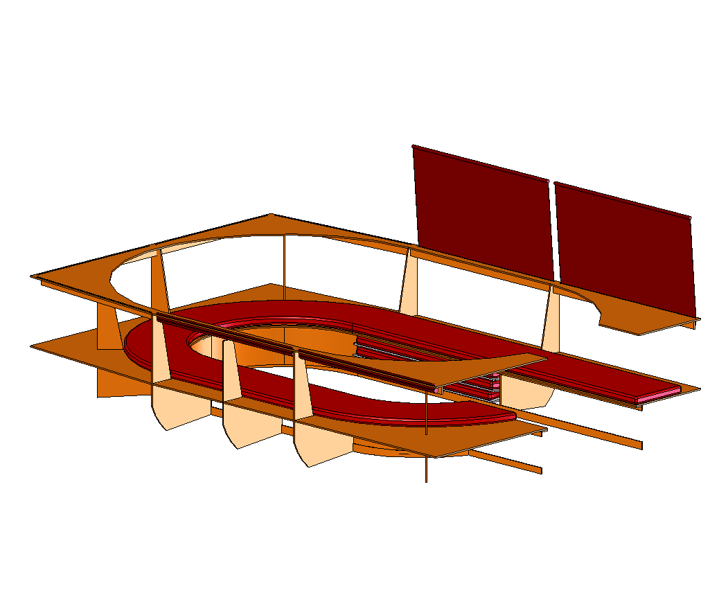
The snug design has undergone several revisions, initially aesthetically but lately the emphasis has been on construction. The modifications ensure that the various structural members that make up the snug marry up to the structural members within the skin of the bus.
The latest revision of the design places the centre points of the two circles that make up either end snug on lines between the structural members in the bus, ie. between window pillars. This means that width of the top of the snug is fractionally more at the front than it is along the sides, although this is only in the order of around an inch. Towards the rear the width is fractionally more again, this is compounded by the fact that the two rear curves don't quite go as far because of the entrance gap. The loss of floor space caused by these changes is minimal.
The initial design for the snug was monolithic in construction. Due to the size of the seat area it will have to be made up of separate parts. In all, 5 pieces will be needed. The curve of the front section is derived from a single sheet of 8'x4'x5/16ths plywood and that section will be assembled as a block and slotted into position. The two straight side sections are mirror images of each other and just over 4' in length, these will be removable to allow the front to slide back for access to the destination blind mechanism. Then the final two curved segments on each side are separate and attached securely to the bulkheads provided by the cupboard and bunk beds.. The intention is to use a strip of angle steel or aluminium to form brackets that perform most of the connections. The boxing for the blinds means that all the way around the top of the snug are pieces of material forming sturdy boxes that will hold everything steady. The snug structure is secured to the structure of the bus by strips of angled aluminium riveted to the main hoops using existing rivet holes. The angle needs to be mounted on the forward side of the front segment so that the front segment can be slid back away from it. It might also be necessary to put some aluminium angle in to support the midpoints of the snug top.
The straight sections of cushion along the sides of the snug are designed to be removable to allow access to the space behind the seats for the storage of small items. Pop fasteners mounted to the seat with corresponding fittings on the back of the cushions will hold the cushions in place. Need to get some foam samples to decide on what thickness and spring are needed for the cushions, and whether some form of backing might be needed. Another option would be for the seats to hinge forward about the bottom to allow access to the storage behind. This sort of storage would be useful for pillows and duvets, although I suspect they will normally get stuffed onto the bunk bed since that will always be easier than accessing the seats.
There is currently no mechanism for accessing the void areas formed by the curves of the seats. Some form of lift of hatch in the seat top would be an option, although inserts to act as cup/bottle holders would be nice. Could possibly combine the two and design the cup/bottle holders to lift out. Suitable plastic molding to act as the bottle holders would need to be sourced or fabricated.
The back of the seat to be constructed from hardboard or flexible ply bent to fit the curve of the seats. The surface is a segment from a cone, hence it should just be curved in a single direction. Additional support is provided by a number of hoops running around the top, middle and bottom. The curve of the seat top is to be constructed using a jigsaw with the blade set at an 11.3degree angle, mounted in a circle jig. Once the top as be cut away the size of the circle can be reduced by an amount to make the mid and lower hoops. The front face of the hoop should be 45mm from the front face of the preceding curve, cut thickness should be absorbed into the back of the hoop giving a hoop depth of around 42mm.
All of the vertical sections utilise a subset of a common pattern which defines the lightening holes, slope of the seat and recesses for support members. A template should be constructed to allow these to be routed out identically. The principal differences are the some pieces do not have the lightening holes, some do not have the back slope and the total depth varies. The shape of the bottom of each has to fit the profile of the floor and this will vary depending upon each sections orientation.
The majority of cupboards beneath the snug seat require curved doors. Layers of thin plywood should be molded over appropriately shaped formers to form a laminate that will hold the shape of the curve.
Blinds are to be fitted into the seat just beneath the top surface of the snug. The blinds pull up through slots in the top surface to cover the windows. The 'top' of the blinds to consist of a piece of 10mm dowel or equivalent so that it doesn't pull back through the slot and will also hook over small fixings at the top of the windows. The aim of this arrangement of blinds is to provide privacy at night but maintain a clean open expanse (ie. no chintzy curtains held back by ties!) during the day. The structures that the blinds attach to will provide extra strength to the top of the snug assemblies, especially in the far corners of the top which are free from supports in the current design.
The top surface of the snug is to be covered in padded cream vinyl. This surface must be removable separately from the snug. Since the vinyl will wrap around the inner face of the top surface an additional rail will have to be provided for attachment of the curved seat back.
The design of the bunks now incorporates a 1900mm blind to mask off the windows. The 3inch space created below the blind can be accessed as storage through holes in the fascia panel. A similar sort of mechanism can be implemented for the rear bed which also need blinds over the windows.
The batteries on a Routemaster are located beneath the stairs. Routemaster electrics run on 24V DC. The chasis should not be considered a ground, all equipment should have a dedicated, insulated, return path. This may have bearing on the mounting of additional dials in the drivers cab which expect a -ve chasis which is often found in cars. Many owners also recommend replacing the 4 existing 6V cells with two MOD specification Hawker batteries because of the improved cold starting ability that they provide. Being of newer design they may also take up less space. A seperate 'leisure' battery should be used for running the internals of the bus, these aren't cheap with a 220Ah battery coming in at Ł180 and almost twice the size of the engine batteries.
Ideally low voltage recessed lights would be used, with particular thought being given over to power considerations since these will be mostly run from a car/truck battery. Thought also has to be given to the depth since there isn't that much space between the inner and outer skins of the shell. Research into LED lights, a 15mm fitting for about Ł6.31, 30mm fittings for about Ł10.75.
Provision needs to be made for an inverted 240V supply to the desk and snug areas on the upper deck and the kitchen area on the lower deck. A 12V supply will be needed by the water pumps & refrigerator.
Liquid Propane Gas provides the most effective means of running heating and refrigeration supplies in the living areas when the main engine is not running. The proposal is to mount the LPG canister in the rear platform area beneath the stairs. The only concern is that this is close to the electrics which might be considered a safety risk. In the event of a fire it could also be considered to be in the escape path from both the upper and lower salons. However, because it's situated on the open rear platform in the event of a gas escape there shouldn't be a buildup of gas because it is free to disperse.
All of the kitchen and bathroom apparatus requiring gas should be located on the offside, since this requires less gas plumbing, which means less things to go wrong. Gas detectors should be fitted in the gas storage area, and low level ventilation to ensure that any leaking gas does drain out of the bottom.
Water tanks can probably be fitted below the floor. The fuel tank is located approximately midway down the offside of the body below the floor. There should be a corresponding void on the nearside, although it may be occupied by some form of compressor for the air brakes or gearbox. The fuel tank itself is 29gallons, 130litres. A typical 6 person motor home has tanks for around 100litres of fresh water and 80 litres of waster water, the 20l discrepancy being the cassette toilet which can handle 17l.
Forward of the above bay there is an empty bay on the nearside. On the opposite side this contains the oil reservoir. Behind this there should be a 2'4" bay as part of the RML chassis. Behind this again are two bays either side of the rear sub frame, which could provide space for water/ waste tanks, although their width is slightly less when compared to the aforementioned bays. Waste tank needs some form of sump and discharge pipe, water tank needs a filler and water pump.
Bathroom area is liable to be damp due to use of showers, etc... Need to use marine grade ply and ensure that it is thoroughly waterproofed. A small footprint shower pan will need to be found, usually these are 700mm which is slightly too large for the 2'6" internal size provisionally allocated to the two rooms. The size of the step around the rear seats is estimated at 31" from the internal face of the side wall, if this were extended to become the wall of the bathrooms then the internal dimensions should be able to accommodate a standard 700mm shower pan.
Need to frost the windows in the bathroom area. Can either use permanent etching paste, spray on etching, or film. Later is probably the best option at the moment since paste can be difficult to control over a large area and the spray on etching may wash off in the damp environment.
The toilet would be a cassette toilet flushed from the main water tank. The problem is that either the cassette has to be removed via the passageway, or a sizeable hole has to be cut into the shell of the bus which will need suitable reinforcement since the inner panels are stress bearing.
It makes most sense to situate the fresh water tank on the offside and the waste water tank on the nearside. Reasoning is because most of the kitchen and bathroom apparatus which generates waste water requires warm water, eg. the kitchen sink and shower which is pumped under pressure. Waste water flows under gravity, therefore it needs to be situated above the waste water tank. Routing pipes waste pipes under the floor is going to be tricky or impossible. Because the refrigerator and cooker will take up space on the offside kitchen the sink will have to go on the nearside, therefore the waste tank has to be on the nearside. The toilet requires freshwater to flush and disposal is through the cassette mechanism, so it can be located on the offside. Shower room to contain a corner hand basin, mirror and shaver power supply.
To minimise space, doors will be of the sliding variety, around a standard door with wide (2'6"). Both doors to have a lip around the bottom to prevent water egress from the bathroom, this also provides a mounting point for the lower slide rail. Door portals to have rounded corners, radiused to match the radius on the windows, ie. 4".
It should be noted that the forward face of the wheel arches is sloping, with the bottom point some 9" forward of the window pillar. This will need to be taken into account when fitting out the bathrooms, either being retained as a sloping portion of the wall, or boxed out into a shelf.
Refrigerator. This take up a considerable amount of space which it might not be possible to find within the galley area due to the wheel arches taking up too much space. Since the toilet bathroom does not need the full 6' allocated to it, it should be possible to fit the refrigerator in the area around the half bay on the offside.
A 4 burner hob will be set in the work top on the offside. The intention is to situate the cooker under the work top, however the clearance between the cooker and the top of the wheel arch is very tight. It currently looks like the cooker will have to impinge on the wheel-arch space by about 2inches. As long as the wheel arch boxes aren't structural this isn't too bad. It should be noted that the rear suspension springs are located just forward of the bulkhead between the platform and lower salon, these will undoubtedly come right to the bottom edge of the seat, therefore the oven will have to sit forward rather than towards the rear since the forward portion of the wheel arch will hopefully just be fresh air.
Kitchen Sink located in the centre of the nearside work top. Waste water tank is located slightly forward below the nearside shower room. Fresh water to be pumped from the tank below the toilet on the offside.
The nearside rear platform wall contains a window making it difficult and undesirable to place any shelves in the kitchen area in front. The offside platform wall is solid since it is backed by the rear stairs, this will allow a series of shelves up to 15" deep to be fitted. Shelves should have both a rail across the front about 1½" above the shelf level, and a small lip at shelf level to stop items from sliding off of the shelves whilst cornering.
Small cupboards could be fitted above the windows. These need to be kept as low profile as possible to avoid overcrowding the area at head height, and, possibly more importantly, to avoid fouling the bell cord which runs along the nearside. Even with these constraints it should still be possible to fit a cupboard around 12" deep. Doors should open upwards on stays, cupboards should be fitted with a similar rail and lip mechanism to that mentioned above for the shelves.It might be worth incorporating some for of extraction mechanism over the hobs.
Hot Water boiler. Ideally this would be located somewhere on the offside near both the gas supply and fresh water tanks. Somewhere beneath the stairs seems most appropriate but it is dependent upon size. It might make more sense to move it into one of the bathrooms, probably the shower room.
The fresh water pump should be mounted beneath the floor alongside the water tanks, or possibly submersed within the water tank itself. Both fresh and waste water tanks need some form of drainage sump. The drainage from the waste water tank should be discharged through a flexible pipe so that it can be run of into a suitable drain.
Gas supply. Ideally the gas bottles would be located beneath the stairs, although the luggage rack, which is the obvious place, is directly over the battery tray. There should be some space underneath the lower steps but I'm not sure how much, or whether it currently has another use. Any gas location needs vent holes in the bottom to allow the heavier than air gas to escape downwards. Whilst I can fit all of the pipework up myself a gas engineer will have to commission the system.
Traditional colours for London buses are Red and Cream, so it makes sense to follow that colour scheme through into the soft furnishings if possible. Ideally the seats would be a leather of some sort, although a dark crimson brocade type material may prove as long lasting and more comfortable to sleep on than leather.
Where possible all wooden surfaces should be a light cream wood of some flavour, with a semi-gloss varnish. Metal surfaces should be stainless steel. The upper portions of both salons, from the window line up, should be painted pale cream. The lower portions, where visible should be painted a maroon red to match the set cushions. The panelling on the exterior of the bathrooms should be light wood if possible, otherwise a rail at window height with maroon below and cream above. A similar approach could be taken with the cupboard and bunk facings in the upper salon.